
Beyond the Cooling Towers: The Engineering Heartbeat of Nuclear Reactors
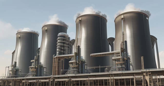
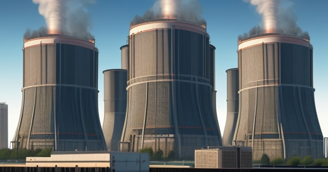
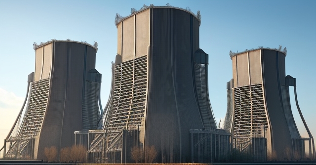
When you picture a nuclear power plant, you might first envision those iconic, towering cooling structures releasing plumes of steam. But while visually striking, these towers are merely the plant’s radiators, dissipating waste heat. The true core, the engine that harnesses the power of the atom, is the nuclear reactor itself. Often hidden behind metres of concrete and steel containment, the reactor is a complex piece of engineering whose appearance varies significantly depending on its purpose, era, and specific design. So, what does a nuclear reactor actually look like? Let’s lift the veil on this vital, often misunderstood, structure.
Understanding the physical appearance of a nuclear reactor isn’t just about curiosity; it reveals the fundamental principles of nuclear physics and the intricate engineering required for controlled energy generation. We’ll explore the basic building blocks common to most reactors, delve into how different designs manifest visually, and even look back at the surprising appearance of the world’s first self-sustaining nuclear chain reaction device and peek at future possibilities like fusion reactors.
The following points summarize key features of nuclear reactors:
- Cooling towers serve as radiators for dissipating heat.
- The reactor is the core of energy production, utilizing fission.
- Total systems ensure safety and energy transfer in a nuclear power plant.

The Fundamental Principle: Controlled Fission and the Need for Structure
At its heart, a nuclear reactor’s primary function is to initiate and control a nuclear chain reaction, typically fission. Fission is the process where the nucleus of a heavy atom, like Uranium-235 (U-235), is split when it absorbs a neutron. This splitting releases a tremendous amount of heat energy, along with more neutrons. If these released neutrons hit other fissile atoms, they can cause further fissions, leading to a self-sustaining chain reaction.
The appearance of a reactor is dictated by the need to manage this powerful, potentially runaway process. You need structures to hold the fuel, control the neutron population (and thus the reaction rate), remove the immense heat generated, and contain everything safely. The physical components we see (or conceptualize within the vessel) are direct responses to these functional requirements. Imagine trying to contain and gently release the energy of countless miniature atomic explosions happening every second – the reactor’s structure is the sophisticated cage built for this task.
The heat produced is the desired output. In most power reactors, this heat is transferred to a fluid called a coolant. This coolant then typically boils water elsewhere in the plant to produce steam. This steam spins a turbine connected to a generator, creating electricity. So, the reactor’s appearance includes not just the core components doing the splitting, but also the systems designed to capture and transfer that energy.
| Component | Function |
|---|---|
| Fuel Assemblies | Contain fuel rods and enable fission reactions. |
| Control Rods | Absorb neutrons to control the reaction rate. |
| Coolant | Removes heat and prevents fuel overheating. |
The Core Anatomy: Fuel Assemblies and Control Rods
When we talk about the ‘core’ of a fission reactor, we are referring to the central region where the nuclear chain reaction takes place. The core doesn’t look like a glowing orb; it’s a highly structured arrangement of materials. The most visually defining elements inside the core are the fuel assemblies and the control rods.
-
Fuel Assemblies: These are bundles of fuel rods. Think of them like carefully arranged packages. A fuel rod is typically a long, slender tube, often made of a zirconium alloy, packed with small, ceramic pellets of enriched uranium dioxide. These pellets, usually only about the size of your fingertip, are where the fission primarily occurs. A fuel assembly might contain hundreds of these rods held together by a metal framework. Inside the reactor vessel, many fuel assemblies are arranged in a precise lattice pattern.
-
Control Rods: Interspersed among the fuel assemblies are the control rods. These rods (or sometimes blades) are made of materials that strongly absorb neutrons, such as cadmium, boron, or hafnium. Physically, they look like sturdy metal rods or cruciform (cross-shaped) blades. Their appearance is distinct from the fuel; they are smooth and often darker. By inserting the control rods further into the core, you absorb more neutrons, slowing the chain reaction or shutting it down. Withdrawing them allows the reaction to speed up. Their movement, controlled remotely, is the primary way operators regulate the reactor’s power level.
Surrounding the fuel assemblies and control rods within the core is the coolant medium, which we’ll discuss next. In some designs, a moderator material (often water or graphite) is also present to slow down the fast neutrons released during fission, making them more likely to cause further fission in U-235. The arrangement of fuel, moderator, and coolant is the intricate internal structure of the reactor core itself.
Containment and Coolant: The Protective Layers
Beyond the immediate arrangement of fuel and control rods, the reactor’s appearance involves several layers of containment and the system that handles the critical task of cooling. The core components described above are housed within a primary boundary:
-
The Pressure Vessel or Pressure Tubes: In most common power reactors (like Pressurized Water Reactors or Boiling Water Reactors), the core sits inside a massive steel vessel, known as a reactor pressure vessel. These vessels are enormous, thick-walled steel cylinders, designed to withstand immense pressure and temperature. They can weigh hundreds, sometimes over a thousand, tonnes. Their exterior is often covered in pipes and instrumentation. In other designs, like the Canadian CANDU or Russian RBMK, the fuel is contained not in a single large vessel, but within many individual pressure tubes running through a large block of moderator material. This changes the internal look dramatically, presenting a lattice of tubes rather than an open vessel cavity.
-
The Coolant System: A fluid, the coolant, constantly flows through the core, surrounding the fuel rods. This fluid is essential for transferring the heat away and preventing the fuel from melting (a meltdown). Common coolants are ordinary water (light water), heavy water, gases (like helium or carbon dioxide), or even liquid metals (like sodium). The coolant loops involve pipes, pumps, and heat exchangers, contributing to the overall plumbing-like appearance surrounding the reactor vessel.
Finally, the entire reactor system – the vessel, coolant loops, and associated components – is enclosed within a robust containment structure. This is the most visible part of the reactor building itself, often a massive dome or a reinforced concrete building with walls metres thick, sometimes lined with steel. Its purpose is to prevent the release of radioactive materials into the environment in the extremely unlikely event of a severe accident. This containment structure is a defining visual feature of the overall reactor building, a symbol of the multiple layers of safety engineering involved.
| Layer | Purpose |
|---|---|
| Pressure Vessel | Holds the reactor pressure and prevents leaks. |
| Coolant System | Transports heat away from the core. |
| Containment Structure | Prevents radioactive material release. |
Diversity in Design: Light Water Reactors (PWR & BWR)
While the basic principles are shared, the specific design choices lead to significant variations in how reactors look, particularly in their steam generation systems. The most prevalent types globally are Light Water Reactors (LWRs), which use ordinary water as both coolant and moderator. The two main variants, Pressurized Water Reactors (PWRs) and Boiling Water Reactors (BWRs), differ fundamentally in their steam production and this affects their overall system layout.
-
Pressurized Water Reactors (PWRs): In a PWR, the water in the reactor vessel (the primary loop) is kept under very high pressure, high enough that it doesn’t boil even at temperatures over 300°C. This superheated water is then pumped to separate large heat exchangers called steam generators. These are massive, tall vessels (often weighing around 800 tonnes each, as seen in plants like Pickering) where the hot, pressurized water from the primary loop flows through tubes, transferring heat to a secondary loop containing lower-pressure water. This lower-pressure water boils, producing the steam that drives the turbine. Visually, a PWR system includes the reactor vessel connected by large pipes to multiple, imposing steam generators, all within the containment building.
-
Boiling Water Reactors (BWRs): A BWR simplifies this by allowing the water to boil directly within the reactor pressure vessel. The core operates at a lower pressure than a PWR, and the heat generated causes the water surrounding the fuel rods to turn into steam right there in the primary loop. This steam is then sent directly to the turbine. From an appearance standpoint, a BWR integrates the steam generation into the reactor vessel itself. This means there are no separate, large steam generators; the vessel is larger than a PWR vessel for a similar power output, as it needs space for the steam to separate from the water. The piping connecting the vessel to the turbine is also a direct link for steam.
These differences in how steam is generated mean that while the core components (fuel, rods) are similar, the vessels, piping, and the presence or absence of massive steam generators give PWR and BWR plants distinct internal layouts and component appearances within their containment structures.
Beyond LWRs: Heavy Water and Other Fission Designs
Not all power reactors use light water. Other designs offer different appearances and functional benefits, often linked to the choice of moderator or coolant, or the fuelling method.
-
Heavy Water Reactors (e.g., CANDU): Reactors like the Canadian Deuterium Uranium (CANDU) design use heavy water (deuterium oxide, D₂O) as both moderator and coolant. Heavy water is much less absorbent of neutrons than light water, allowing these reactors to use natural uranium fuel, which is less enriched than the fuel used in LWRs. Structurally, CANDU reactors look different internally. Instead of a single large pressure vessel, the fuel bundles sit inside hundreds of horizontal pressure tubes. These tubes pass through a large, low-pressure tank (the ‘calandria’) filled with the heavy water moderator. Hot heavy water coolant flows through the pressure tubes. This pressure tube design allows for a unique feature: on-load refuelling, meaning fuel can be replaced while the reactor is operating, using complex fuelling machines attached to the ends of the tubes. The appearance involves a large calandria structure and numerous pressure tubes accessible by machinery.
-
Gas-Cooled Reactors (e.g., AGRs): Older designs, like the Advanced Gas-cooled Reactors (AGRs) used in the UK, use graphite as a moderator and carbon dioxide gas as a coolant. The core is typically housed in a large concrete pressure vessel. Their appearance differs with the large gas circulation systems and steam generators integrated or closely coupled to the concrete vessel.
-
Graphite-Moderated, Water-Cooled Reactors (e.g., RBMK): The RBMK design (like the one at Chernobyl) also uses graphite as a moderator but employs water as a coolant in pressure tubes. These are physically very large reactors due to the volume of the graphite block. While sharing the pressure tube concept with CANDU, their large graphite moderator structure and vertical tube orientation give them a distinct appearance, often requiring large buildings to house the core.
These variations highlight that while the goal (controlled fission) is the same, the materials chosen for moderator and coolant, and the engineering approach to containing pressure and managing fuel, directly shape the physical form and complexity of the reactor’s internal and immediately external components.
A Glimpse into the Past: The Appearance of Early Reactors
If we travel back in time, the appearance of the world’s first self-sustaining nuclear reactor was strikingly different from the complex engineered systems we see today. The device known as Chicago Pile-1 (CP-1), built in a squash court under the stands of Stagg Field at the University of Chicago, achieved criticality on December 2, 1942, under the direction of physicist Enrico Fermi as part of the Manhattan Project.
CP-1 didn’t have a steel pressure vessel, coolant loops, or a containment building in the modern sense. It literally looked like a pile. It was constructed from layers of graphite blocks, which served as the moderator, interspersed with chunks and smaller blocks of uranium metal and uranium oxide, the fuel. As described by those who built it, it was a roughly spherical structure, flattened on the bottom, that reached about 20 feet (6 metres) tall and 25 feet (about 7.5 metres) wide at its widest point. It was assembled layer by layer.
Control was manual; some layers contained slots where cadmium-coated wooden or plastic rods (the crude predecessors of modern control rods) could be inserted or withdrawn by hand. One rod was even attached to a rope with an axe poised to cut it in case of emergency, allowing gravity to drop the rod into the pile. There was no dedicated cooling system beyond the natural air convection; it operated at very low power levels (about half a watt initially). Its appearance was that of stacked blocks, a testament to the pioneering, experimental nature of early nuclear physics, a world away from the polished metal and concrete of today’s facilities.
Looking to the Future: Small Modular Reactors (SMRs)
The appearance of future fission reactors is likely to include variations on current themes, particularly with the advent of Small Modular Reactors (SMRs). As the name suggests, SMRs are designed to be significantly smaller than traditional large power reactors, typically producing less than 300 MWe. Their “modular” aspect means they are designed to be largely fabricated in factories and then transported as complete or large components to the plant site for assembly.
While many SMR designs are based on scaled-down versions of existing light water reactor technology (PWRs or BWRs), their smaller size allows for potentially more compact and simplified plant layouts. Some designs integrate components like the steam generator or even the turbine into a single module or vessel, reducing the external piping and complexity seen in larger plants. This could lead to reactor buildings that appear less sprawling and perhaps more streamlined or standardized.
Other SMR designs explore different technologies, such as fast reactors or high-temperature gas reactors, which may have different internal configurations related to their coolants (e.g., liquid metal or gas) and fuel forms. The emphasis on modularity suggests that the visual construction process and the site footprint of SMR plants will look notably different from traditional large reactor construction, with large factory-built modules being lifted into place.
The Different Beast: What Fusion Reactors (ITER) Look Like
While fission reactors split heavy atoms, fusion reactors aim to merge light atomic nuclei (like isotopes of hydrogen, deuterium and tritium) to release energy, the same process that powers the sun. The appearance of a fusion reactor is radically different from its fission counterpart because the physics involved requires an entirely different approach to containing the reaction.
Instead of a solid core of fuel rods and control rods within a pressure vessel, fusion reactors, like the large-scale International Thermonuclear Experimental Reactor (ITER) being built in the South of France, are dominated by complex magnetic confinement systems. The most common design is the tokamak. A tokamak looks like a gigantic, hollow donut or torus, surrounded by massive, intricate superconducting magnets and vacuum pumps. Within this toroidal chamber, a superheated plasma (an ionized gas hotter than the sun’s core) is generated and held in place by the powerful magnetic fields.
The ITER facility, when complete, will not look like a traditional power plant with a reactor building and cooling towers (though it will have heat exchange systems). The centerpiece is the colossal tokamak device itself – a complex arrangement of vacuum vessel segments, divertors, heating systems, and diagnostic equipment, all encased within a vast cryostat and surrounded by immense magnet coils and support structures. Its appearance is that of an extremely sophisticated, large-scale scientific experiment, a testament to the challenge of replicating stellar processes on Earth, and bearing little visual resemblance to the nuclear piles or pressure vessels of fission technology.
The Scale of Engineering: Massive Components and Structures
One of the most striking aspects of modern nuclear reactors is the sheer scale of their key components and the structures that house them. While the fuel pellets are small, the vessels and associated equipment are monumental.
We’ve mentioned the pressure vessel, which can be one of the largest single forged or welded components ever manufactured, weighing thousands of tonnes. Installing this vessel into the reactor building is a major engineering feat requiring immense cranes. Similarly, in PWRs, the steam generators are towering structures within the containment building, often tens of metres tall and weighing hundreds of tonnes each.
The containment structure itself is built to withstand significant internal pressures and external impacts. Its concrete walls are typically 1-2 metres thick, reinforced with vast amounts of steel rebar, and sometimes lined with a steel shell. The scale of this structure is visually imposing, often appearing as a large, reinforced dome or cylindrical building designed as the ultimate barrier. Even the pumps, valves, and piping in the primary coolant loops are large and robust, built to handle high pressures and temperatures.
Walking through a nuclear power plant’s protected areas, you are confronted with this massive scale at every turn – thick walls, heavy doors, large diameter pipes, and huge components dwarfing human visitors. This physical scale is a direct reflection of the immense forces and energies being managed within the reactor system.
| Aspect | Description |
|---|---|
| Pressure Vessel | One of the largest components, weighing thousands of tonnes. |
| Steam Generators | Tall structures, tens of metres high, often weighing hundreds of tonnes. |
| Containment Structure | Concrete walls with thicknesses of 1-2 metres designed to prevent leaks. |
The Legacy and Global Presence
The physical appearance of nuclear reactors tells a story of technological evolution, from the basic stacked blocks of CP-1 to the complex vessels and magnetic cages of today and tomorrow. These structures are not merely engineering marvels; they are tangible symbols of humanity’s capacity to harness atomic energy, with a legacy intertwined with both power generation and the specter of nuclear weapons (many early reactor designs, like those at Hanford, Washington, were built specifically to produce plutonium for weapons, leveraging similar fission principles but with different operational goals and thus appearances tailored for that purpose).
Globally, over 400 nuclear fission reactors are in operation across more than 30 countries, providing approximately 9% of the world’s electricity. While each plant has its unique site layout and building architecture, the core components – the vessel, fuel arrangements, control rod drive mechanisms, coolant systems, and containment buildings – share fundamental visual characteristics dictated by the physics they contain. From the iconic domes of many Western plants to the distinct buildings housing pressure tube reactors, their appearance is a footprint on the landscape, representing a significant part of our global energy infrastructure and scientific history.
Conclusion: Unveiling the Complex Engine
So, what does a nuclear reactor look like? It’s not a single image, but a range of forms. It’s the intricate lattice of fuel assemblies and control rods within a heavy pressure vessel or a network of pressure tubes. It’s the massive steam generators linked by robust piping in some designs, and their absence in others. It’s the immense, metres-thick concrete and steel shell of the containment structure that forms the visible boundary of the reactor building.
Looking back, it’s the surprisingly simple stack of graphite and uranium blocks that was Chicago Pile-1. Looking forward, it’s the more compact, potentially integrated modules of SMRs or the complex, magnet-dominated torus of a fusion tokamak like ITER. While the core reaction is hidden from view, the structures and components required to contain, control, and utilize that power create a diverse gallery of sophisticated engineering forms. Understanding the physical appearance of a reactor helps us appreciate the complex science and the scale of the challenge involved in safely generating power from the atom, revealing the intricate heart that beats within the nuclear power plant.
what does a nuclear reactor look likeFAQ
Q:What are the main components of a nuclear reactor?
A:The main components include fuel assemblies, control rods, coolant systems, and containment structures.
Q:How do different types of reactors differ in appearance?
A:Different types of reactors, such as PWRs and BWRs, vary in their internal layouts and the presence of steam generators.
Q:What is the role of containment structures?
A:Containment structures prevent the release of radioactive materials in the event of an accident.
留言